Electronic circuit projects Circuit Circuit Diagram Circuit Explanation. The IC 555 timer circuits rely on three 5K resistors to produce a voltage divider at pins 1 and 8. The circuit diagram above is for a one-minute timer based on the IC 555.To get varying times, all you have to do is adjust the values of the resistor R1. Simple Adjustable Timer Circuit with 555 IC. Using simple 555 timer we can design an adjustable timer switch. This circuit is flexible to adjust required time. Circuit Diagram Components. 555 timer; Electrolytic capacitor - 470 uf; ceramic capacitor - 0.1nF; Resistors 120k ohm 10k ohm; Relay -12v; Push button; Working Learn how to use the 555 timer IC to create blinking lights, alarms, musical instruments, and more. The tutorial covers the pinout, modes, and circuits of the 555 timer with examples and calculator.

Note: You can also use the formula to make a timer circuit by changing the capacitor value and make the resistance value constant. Related Project: Traffic Light Control Electronic Project using 555 Timer; 5 Minutes Timer Circuit: Similarly, in the 5-minute timer circuit, we will be using the above formula to get the exact resistance of the
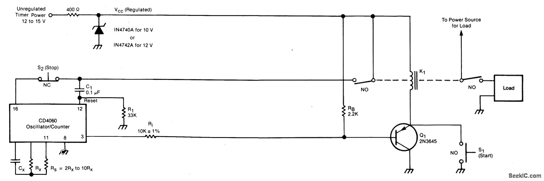
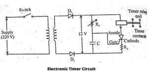
Adjustable Timer Circuit Diagram with Relay Output
Here, a 4-step programmable timer circuit is shown, but you can add more number of 4060 stages to increase the number of cascaded outputs, as desired. I am passionate about inventing, designing electronic circuits and PCBs, and helping hobbyists bring their projects to life. That is why I founded homemade-circuits.com, a website where I
This simple digital timer circuit can be used to obtain timing output through selectable ranges, which can be set from 0 to 99 second, with 1 second interval, 0 to 990 seconds with 10 second interval, and 0 to 99 minutes with 1 minute interval. All these timing outputs can be visualized and tracked through a 2 digit common anode LED display.
Electronic Timer Circuit Circuit Diagram
An electronic timer circuit is an essential component in many electronic systems and devices. It allows you to control the timing and duration of various operations, such as turning on/off lights, motors, or other components after a predefined time interval. Timer circuits find applications in a wide range of fields, including automation, home
